- Velkommen til Elbilforum.no - driftet av Norsk elbilforening.

Denne delen lar deg se alle innlegg laget av dette medlemmet. Merk at du bare kan se innlegg gjort i områder du har tilgang til.
#1
"Nye" TH!NK City produsert fra 2008 - 2012 / Sv: Designing new RLEC boards, any interest?
mandag 06. januar 2025, klokken 17:11 #2
"Nye" TH!NK City produsert fra 2008 - 2012 / Sv: Designing new RLEC boards, any interest?
mandag 06. januar 2025, klokken 15:07
Some progress.  Coding the stm32 program was much bigger task than I expected, but I think it's pretty much working now. I plan to release at least the software and the schematics into github soon.
There was a few hardware bugs (design faults).. CAN bus has H and L reversed, but they can be cleanly fixed in the ribbon cable connector on board side. Then there was a mysterious measurement error in one of the cell voltages.. I feel this is a documentation error in the datasheet, I asked about in the ST forum but no one has replied:
https://community.st.com/t5/power-management/l9963e-in-12s-setup-middle-cell-shows-too-low-voltage/m-p/756642#M12975
Anyone my fix seems to be working and was easy to implement on the existing boards, just connect two adjacent pins with a solder blob.
Next batch of boards will obviously have these fixes included.

(open picture to new tab to enlarge)
Here are the boards in place. I decided to use the six original RLECs that were still functional.
The Double RLEC in bottom left is the master. It is the only one connected to the original CAN bus (ribbon cable). Rest of the Double RLECs are daisy chained using the L9963E two-wire isolated SPI bus. The master card listens to CAN messages and pretends to be all ten RLECs himself.
The daisy chain connecting cables are the 4pin cables that normally connect two RLECs.. I thought everyone has these laying around. If you have two broken RLECs you will have one cable also.
Any configuration of RLEC / Double RLEC can work; you can have any amount of "old" RLECs and you could also have multiple master Double RLECs..
The black box is a Raspberry Pi that is connected to the CAN and also has UART connection to the master RLEC which allows it to flash new firmware into it etc. So I can remotely debug and develop the software inside the house while the battery is in my cold garage..
Here is the RLEC data recorded by the raspberry:
Balance target 4100 mV, balanced cells: 0
Module 00 Reported: 47.70 V Calculated: 47.70 V 34 C Status 0x0
T: -3 -3 -3 -3 -3 -3 -3 -3 -3 -3 -3 -3 ( -3- -3)
V: 4023 3996 3965 3962 3957 3938 3962 3962 3962 3962 3986 4026 (4026-3938 = 88 mV)
Module 01 Reported: 48.13 V Calculated: 48.13 V 29 C Status 0x0
T: -3 -3 -3 -3 -3 -3 -3 -3 -3 -3 -3 -3 ( -3- -3)
V: 4030 4013 4013 4001 3996 3999 3999 3977 4008 4030 4033 4035 (4035-3977 = 58 mV)
Module 02 Reported: 48.31 V Calculated: 48.31 V 27 C Status 0x0
T: -3 -3 -3 -3 -3 -3 -3 -3 -3 -3 -3 -3 ( -3- -3)
V: 4026 4030 4030 4033 4033 3999 4021 4033 4035 4033 4011 4030 (4035-3999 = 36 mV)
Module 03 Reported: 48.45 V Calculated: 48.47 V 29 C Status 0x0
T: -3 -3 -3 -3 -3 -3 -3 -3 -3 -3 -3 -3 ( -3- -3)
V: 4035 4038 4038 4038 4038 4040 4038 4040 4040 4040 4040 4040 (4040-4035 = 5 mV)
Module 04 Reported: 47.99 V Calculated: 48.00 V 30 C Status 0x0
T: -3 -3 -3 -3 -3 -3 -3 -3 -3 -3 -3 -3 ( -3- -3)
V: 4030 4030 4021 4018 3977 3989 3989 3965 3984 3991 4001 4008 (4030-3965 = 65 mV)
Module 05 Reported: 48.02 V Calculated: 48.02 V 27 C Status 0x0
T: -3 -3 -3 -3 -3 -3 -3 -3 -3 -3 -3 -3 ( -3- -3)
V: 4006 4008 4006 4008 4006 3986 4008 4006 4016 4021 3994 3950 (4021-3950 = 71 mV)
Module 06 Reported: 48.31 V Calculated: 48.33 V 25 C Status 0x0
T: -3 -3 -3 -3 -3 -3 -3 -3 -3 -3 -3 -3 ( -3- -3)
V: 4023 4016 4023 4026 4023 4023 4006 4030 4038 4038 4040 4045 (4045-4006 = 39 mV)
Module 07 Reported: 48.29 V Calculated: 48.32 V 29 C Status 0x0
T: -3 -3 -3 -3 -3 -3 -3 -3 -3 -3 -3 -3 ( -3- -3)
V: 4016 4028 4028 4033 4030 4033 4035 4021 4035 4033 3999 4033 (4035-3999 = 36 mV)
Module 08 Reported: 48.35 V Calculated: 48.36 V 31 C Status 0x0
T: -3 -3 -3 -3 -3 -3 -3 -3 -3 -3 -3 -3 ( -3- -3)
V: 4030 4033 4033 4026 4030 4033 4030 4026 4028 4028 4030 4035 (4035-4026 = 9 mV)
Module 09 Reported: 48.13 V Calculated: 48.14 V 30 C Status 0x0
T: -3 -3 -3 -3 -3 -3 -3 -3 -3 -3 -3 -3 ( -3- -3)
V: 4038 4021 4018 3986 3991 3994 3994 3994 3994 4035 4035 4038 (4038-3986 = 52 mV)
Module 10 Reported: 48.37 V Calculated: 48.39 V 2 C Status 0x0
T: -1 -1 -1 -1 -1 -1 -1 -1 -1 -1 -1 -1 ( -1- -1)
V: 4033 4028 4028 4028 4035 4035 4035 4033 4033 4033 4033 4033 (4035-4028 = 7 mV)
Module 11 Reported: 47.80 V Calculated: 47.91 V 2 C Status 0x0
T: -1 -1 -1 -1 -1 -1 -1 -1 -1 -1 -1 -1 ( -1- -1)
V: 4030 3979 3977 3974 3972 3969 3908 3989 3991 4038 4038 4043 (4043-3908 = 135 mV)
Module 12 Reported: 47.82 V Calculated: 47.71 V 4 C Status 0x0
T: -1 -1 -1 -1 -1 -1 -1 -1 -1 -1 -1 -1 ( -1- -1)
V: 4033 4035 4033 4038 4035 4035 4035 4035 4033 4038 3328 4030 (4038-3328 = 710 mV)
Module 13 Reported: 47.35 V Calculated: 47.84 V 3 C Status 0x0
T: -1 -1 -1 -1 -1 -1 -1 -1 -1 -1 -1 -1 ( -1- -1)
V: 4008 4018 4021 3977 3974 3967 3969 3969 3965 3967 3972 4035 (4035-3965 = 70 mV)
Module 14 Reported: 47.54 V Calculated: 47.54 V 3 C Status 0x0
T: -1 -1 -1 -1 -1 -1 -1 -1 -1 -1 -1 -1 ( -1- -1)
V: 4035 4033 4008 4006 4006 3413 3999 4006 4006 4008 4011 4011 (4035-3413 = 622 mV)
Module 15 Reported: 48.01 V Calculated: 48.14 V 2 C Status 0x0
T: -1 -1 -1 -1 -1 -1 -1 -1 -1 -1 -1 -1 ( -1- -1)
V: 4030 4006 4008 3996 3996 4004 4006 4018 4006 4023 4018 4028 (4028-3996 = 32 mV)
06.01 15:40: Cell (3328-4045)=717 mV, Temp (-3--1), Pack 48.47 V, Status 0x0
Modules 00-09 are Double RLECs, 10-15 are original. There seems to be some difference in the measured temperatures (-3 vs -1) but I don't think that's critical. Also the "board temperature" in the top row is chip internal junction temperature for the Double RLECs, that's why it's so high (~30C). MLEC shouldn't be interested in those..
There is some severe imbalance in modules 12 and 14.. I will have to remove those batteries and charge (or replace) the low voltage cells.
Next step will be to wire up the HV cables and connect the battery to the car, to see if MLEC likes what it's seeing.. I can also listen MLEC<->RLEC communication with the Raspberry. I will made extension cables so I can connect the battery to the car without moving it any closer.
Coding the stm32 program was much bigger task than I expected, but I think it's pretty much working now. I plan to release at least the software and the schematics into github soon.There was a few hardware bugs (design faults).. CAN bus has H and L reversed, but they can be cleanly fixed in the ribbon cable connector on board side. Then there was a mysterious measurement error in one of the cell voltages.. I feel this is a documentation error in the datasheet, I asked about in the ST forum but no one has replied:
https://community.st.com/t5/power-management/l9963e-in-12s-setup-middle-cell-shows-too-low-voltage/m-p/756642#M12975
Anyone my fix seems to be working and was easy to implement on the existing boards, just connect two adjacent pins with a solder blob.
Next batch of boards will obviously have these fixes included.
(open picture to new tab to enlarge)
Here are the boards in place. I decided to use the six original RLECs that were still functional.
The Double RLEC in bottom left is the master. It is the only one connected to the original CAN bus (ribbon cable). Rest of the Double RLECs are daisy chained using the L9963E two-wire isolated SPI bus. The master card listens to CAN messages and pretends to be all ten RLECs himself.
The daisy chain connecting cables are the 4pin cables that normally connect two RLECs.. I thought everyone has these laying around. If you have two broken RLECs you will have one cable also.
Any configuration of RLEC / Double RLEC can work; you can have any amount of "old" RLECs and you could also have multiple master Double RLECs..
The black box is a Raspberry Pi that is connected to the CAN and also has UART connection to the master RLEC which allows it to flash new firmware into it etc. So I can remotely debug and develop the software inside the house while the battery is in my cold garage..
Here is the RLEC data recorded by the raspberry:
Balance target 4100 mV, balanced cells: 0
Module 00 Reported: 47.70 V Calculated: 47.70 V 34 C Status 0x0
T: -3 -3 -3 -3 -3 -3 -3 -3 -3 -3 -3 -3 ( -3- -3)
V: 4023 3996 3965 3962 3957 3938 3962 3962 3962 3962 3986 4026 (4026-3938 = 88 mV)
Module 01 Reported: 48.13 V Calculated: 48.13 V 29 C Status 0x0
T: -3 -3 -3 -3 -3 -3 -3 -3 -3 -3 -3 -3 ( -3- -3)
V: 4030 4013 4013 4001 3996 3999 3999 3977 4008 4030 4033 4035 (4035-3977 = 58 mV)
Module 02 Reported: 48.31 V Calculated: 48.31 V 27 C Status 0x0
T: -3 -3 -3 -3 -3 -3 -3 -3 -3 -3 -3 -3 ( -3- -3)
V: 4026 4030 4030 4033 4033 3999 4021 4033 4035 4033 4011 4030 (4035-3999 = 36 mV)
Module 03 Reported: 48.45 V Calculated: 48.47 V 29 C Status 0x0
T: -3 -3 -3 -3 -3 -3 -3 -3 -3 -3 -3 -3 ( -3- -3)
V: 4035 4038 4038 4038 4038 4040 4038 4040 4040 4040 4040 4040 (4040-4035 = 5 mV)
Module 04 Reported: 47.99 V Calculated: 48.00 V 30 C Status 0x0
T: -3 -3 -3 -3 -3 -3 -3 -3 -3 -3 -3 -3 ( -3- -3)
V: 4030 4030 4021 4018 3977 3989 3989 3965 3984 3991 4001 4008 (4030-3965 = 65 mV)
Module 05 Reported: 48.02 V Calculated: 48.02 V 27 C Status 0x0
T: -3 -3 -3 -3 -3 -3 -3 -3 -3 -3 -3 -3 ( -3- -3)
V: 4006 4008 4006 4008 4006 3986 4008 4006 4016 4021 3994 3950 (4021-3950 = 71 mV)
Module 06 Reported: 48.31 V Calculated: 48.33 V 25 C Status 0x0
T: -3 -3 -3 -3 -3 -3 -3 -3 -3 -3 -3 -3 ( -3- -3)
V: 4023 4016 4023 4026 4023 4023 4006 4030 4038 4038 4040 4045 (4045-4006 = 39 mV)
Module 07 Reported: 48.29 V Calculated: 48.32 V 29 C Status 0x0
T: -3 -3 -3 -3 -3 -3 -3 -3 -3 -3 -3 -3 ( -3- -3)
V: 4016 4028 4028 4033 4030 4033 4035 4021 4035 4033 3999 4033 (4035-3999 = 36 mV)
Module 08 Reported: 48.35 V Calculated: 48.36 V 31 C Status 0x0
T: -3 -3 -3 -3 -3 -3 -3 -3 -3 -3 -3 -3 ( -3- -3)
V: 4030 4033 4033 4026 4030 4033 4030 4026 4028 4028 4030 4035 (4035-4026 = 9 mV)
Module 09 Reported: 48.13 V Calculated: 48.14 V 30 C Status 0x0
T: -3 -3 -3 -3 -3 -3 -3 -3 -3 -3 -3 -3 ( -3- -3)
V: 4038 4021 4018 3986 3991 3994 3994 3994 3994 4035 4035 4038 (4038-3986 = 52 mV)
Module 10 Reported: 48.37 V Calculated: 48.39 V 2 C Status 0x0
T: -1 -1 -1 -1 -1 -1 -1 -1 -1 -1 -1 -1 ( -1- -1)
V: 4033 4028 4028 4028 4035 4035 4035 4033 4033 4033 4033 4033 (4035-4028 = 7 mV)
Module 11 Reported: 47.80 V Calculated: 47.91 V 2 C Status 0x0
T: -1 -1 -1 -1 -1 -1 -1 -1 -1 -1 -1 -1 ( -1- -1)
V: 4030 3979 3977 3974 3972 3969 3908 3989 3991 4038 4038 4043 (4043-3908 = 135 mV)
Module 12 Reported: 47.82 V Calculated: 47.71 V 4 C Status 0x0
T: -1 -1 -1 -1 -1 -1 -1 -1 -1 -1 -1 -1 ( -1- -1)
V: 4033 4035 4033 4038 4035 4035 4035 4035 4033 4038 3328 4030 (4038-3328 = 710 mV)
Module 13 Reported: 47.35 V Calculated: 47.84 V 3 C Status 0x0
T: -1 -1 -1 -1 -1 -1 -1 -1 -1 -1 -1 -1 ( -1- -1)
V: 4008 4018 4021 3977 3974 3967 3969 3969 3965 3967 3972 4035 (4035-3965 = 70 mV)
Module 14 Reported: 47.54 V Calculated: 47.54 V 3 C Status 0x0
T: -1 -1 -1 -1 -1 -1 -1 -1 -1 -1 -1 -1 ( -1- -1)
V: 4035 4033 4008 4006 4006 3413 3999 4006 4006 4008 4011 4011 (4035-3413 = 622 mV)
Module 15 Reported: 48.01 V Calculated: 48.14 V 2 C Status 0x0
T: -1 -1 -1 -1 -1 -1 -1 -1 -1 -1 -1 -1 ( -1- -1)
V: 4030 4006 4008 3996 3996 4004 4006 4018 4006 4023 4018 4028 (4028-3996 = 32 mV)
06.01 15:40: Cell (3328-4045)=717 mV, Temp (-3--1), Pack 48.47 V, Status 0x0
Modules 00-09 are Double RLECs, 10-15 are original. There seems to be some difference in the measured temperatures (-3 vs -1) but I don't think that's critical. Also the "board temperature" in the top row is chip internal junction temperature for the Double RLECs, that's why it's so high (~30C). MLEC shouldn't be interested in those..
There is some severe imbalance in modules 12 and 14.. I will have to remove those batteries and charge (or replace) the low voltage cells.
Next step will be to wire up the HV cables and connect the battery to the car, to see if MLEC likes what it's seeing.. I can also listen MLEC<->RLEC communication with the Raspberry. I will made extension cables so I can connect the battery to the car without moving it any closer.
#3
"Nye" TH!NK City produsert fra 2008 - 2012 / Sv: Enerdel lithium batteri kasser.
fredag 08. november 2024, klokken 17:42
This is a great topic! The precharge resistor mod in first page is a must for everyone who ever disassembles the pack.
I'm not sure about the breather box, but the idea of replaceable moisture collector is great.
There isn't much breathing originally in the battery, there is no way for water to get out. I thought I maybe fill the box with CO2 or nitrogen, and add some "cat litter" bags to the spare area in the middle.. It's even possible to make a service hatch to the bottom, to replace the bags. In theory you could drill the hole while battery is in the car, but of course some careful thinking is needed.
#4
"Nye" TH!NK City produsert fra 2008 - 2012 / Sv: Designing new RLEC boards, any interest?
fredag 18. oktober 2024, klokken 10:14Sitat fra: babjerke på tirsdag 15. oktober 2024, klokken 23:37The card looks nice - which IC did you go for?
It is the ST9963E.
I draw a schematic with the much cheaper BQ76952, but turns out once you add the isolation components and external balancing fets, the price is almost the same and it's much more complex circuit.
#5
"Nye" TH!NK City produsert fra 2008 - 2012 / Sv: Eltek-Valere charger firmware and bootloader
mandag 07. oktober 2024, klokken 20:34
Yeah.. for example Tesla charger CAN messages are quite well known:
https://www.diyelectriccar.com/threads/tesla-10kw-open-source-charger-controller.187345/
And those are quite easily available from ebay etc.
https://www.diyelectriccar.com/threads/tesla-10kw-open-source-charger-controller.187345/
And those are quite easily available from ebay etc.
#6
"Nye" TH!NK City produsert fra 2008 - 2012 / Sv: Eltek-Valere charger firmware and bootloader
mandag 07. oktober 2024, klokken 09:26
If anything else fails, it should be possible to do a device that sits on the CAN bus and translates the messages.
#7
"Nye" TH!NK City produsert fra 2008 - 2012 / Sv: Designing new RLEC boards, any interest?
mandag 07. oktober 2024, klokken 08:45
Just got photos from Elecrow, they have finished the boards and are shipping now.
Then I can start on the software..
#8
"Nye" TH!NK City produsert fra 2008 - 2012 / Sv: Enerdel battery module max current?
torsdag 26. september 2024, klokken 20:54
I did some measurement. I measured the internal resistance of Think cells and also Nissan Leaf cells which I also happen to have.
My measurement procedure is simple; I measure the "idle" voltage of cell, then apply 3A charger and measure voltage again. Then we get R=Vdiff/3A
Think cells: 15mV --> 5.0 milliohms
Leaf cells: 5mV --> 1.7 milliohms
While 5mohm doesn't sound too bad, when I have 22 of cells in series it becomes 0.11 ohm. Even that doesn't sound bad, but if you calculate with 150A, U=R*I = 16.5V.... So 90V battery would drop to 74V during load! And P=U*I so 16.5*150 = 2475 Watts lost as heat in the battery pack...
With Leaf cells, the drop would be only about 5V, and "only" 750W lost as heat in the pack.
The test was conducted in quite cold temperature (+13C). Battery internal resistance decreases when battery heats, and obviously it would heat quite a bit with 2kW internal heater. But I still assume Leaf cell would be 3* better in any temperature.
So, I think I'll use Leaf cells. It's just that those cells are in use and I now need to replace them with something else.
My measurement procedure is simple; I measure the "idle" voltage of cell, then apply 3A charger and measure voltage again. Then we get R=Vdiff/3A
Think cells: 15mV --> 5.0 milliohms
Leaf cells: 5mV --> 1.7 milliohms
While 5mohm doesn't sound too bad, when I have 22 of cells in series it becomes 0.11 ohm. Even that doesn't sound bad, but if you calculate with 150A, U=R*I = 16.5V.... So 90V battery would drop to 74V during load! And P=U*I so 16.5*150 = 2475 Watts lost as heat in the battery pack...
With Leaf cells, the drop would be only about 5V, and "only" 750W lost as heat in the pack.
The test was conducted in quite cold temperature (+13C). Battery internal resistance decreases when battery heats, and obviously it would heat quite a bit with 2kW internal heater.
But I still assume Leaf cell would be 3* better in any temperature.So, I think I'll use Leaf cells. It's just that those cells are in use and I now need to replace them with something else.
#9
"Nye" TH!NK City produsert fra 2008 - 2012 / Sv: Enerdel battery module max current?
torsdag 26. september 2024, klokken 12:46
Heh, I'll continue my monologue. 
https://www.elithion.com/pdf/enerdel/MP320-049.pdf
This is interesting, this pack has similar specs as Think pack, only 32Ah and the dimensions match exactly, except for the battery terminals. This datasheet shows 160A max and 480A pulse discharge (for 10 seconds).. That would be quite enough. The datasheet is from 2012 so even the time period would match Think batteries.
#10
"Nye" TH!NK City produsert fra 2008 - 2012 / Sv: Enerdel battery module max current?
torsdag 26. september 2024, klokken 12:41
While googling I found this:
https://www.greentecauto.com/hybrid-battery/repurposed-batteries/energy/enerdel-nmc-48v-50ah-2-2kwh-brand-new-battery-module
Looks exactly like Think battery except for the + and - terminals? Or is this actually a bit larger as it says 50Ah and Think cells only are like 35Ah?
But anyway even this page says 70A max current, maybe it really is that low.
#11
"Nye" TH!NK City produsert fra 2008 - 2012 / Enerdel battery module max current?
torsdag 26. september 2024, klokken 12:16
Hi,
I'm building an electric motorcycle with 12kW motor and about max 95V battery voltage, and looking for suitable batteries..
As you know I have a few Think Enerdel packs. I could build a 22S pack with these cells to get correct voltage. But I need about 150A current.
"Think City Enerdel Battery Service Manual.pdf" says maximum current for the pack is 140A. But this is for the entire pack, where there's two "chains" of modules in parallel! So for single module the current would be only 70A.
But then again the 140A limit might simple be because there's 170A fuse and the contactors have 200A limit if I remember correctly.. So 140A might not be the module limit but pack limit?
So, anyone know for sure, or do I just try it and after the explosion decide to get some other batteries?
#12
"Nye" TH!NK City produsert fra 2008 - 2012 / Sv: Designing new RLEC boards, any interest?
onsdag 11. september 2024, klokken 11:47Sitat fra: Warlock på tirsdag 10. september 2024, klokken 20:18
I might order one.
Still wondering a bit about the cost tho, PCBWay and similar has reduced cost for card production quite a lot the latest years, so are the components the costly parts for these cards, is it quite large, or is this production done by a local firm, or something else?
Boards and assembly are done by Elecrow, a chinese manufacturer.. It should be one of the cheapest.
Most of the price comes from the components. And also the assembly price is about 250€ total for any amount of cards, so now it plays quite big role when only 16 cards are made.
PCB is quite big (315*100mm) but it still only costs about 4€.. It would have been easy to split in into two, but I figured the connectors and wiring between the cards would easily be more expensive.
The slave card is quite a bit cheaper.
In the meanwhile, I learned that it's actually quite simple to remove the connectors from RLEC cards using a heat gun..

#13
"Nye" TH!NK City produsert fra 2008 - 2012 / Sv: Designing new RLEC boards, any interest?
tirsdag 10. september 2024, klokken 11:08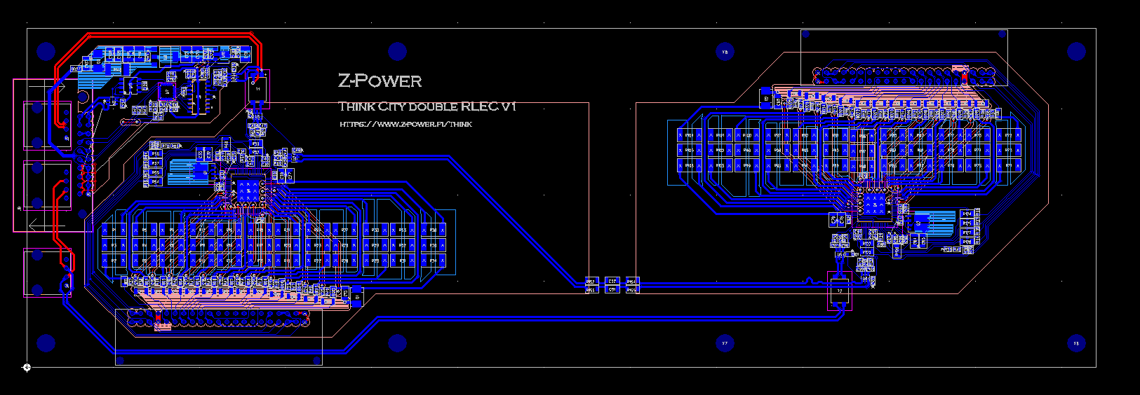
I just ordered a first batch of boards from Elecrow, 16 pieces. So enough for two cars as each card has two RLECs.
The design allows "master" and "slave" cards, masters have 16pin CAN connector like standard RLEC. Then you can daisy chain upto 7 slaves after that one master. So only one master needed in each car.
However since the assembly start cost is so high (~250€) I now ordered only master cards. They can easily be connected as slaves too for testing, and also allows to test a setup with 8 masters and no slaves (only CAN bus connection).
It should be possible to mix old and new style RLECs, if only a few are needed. Then again, it might make sense to replace all and sell the remaining working old RLECs..
The price of the card is much higher than I anticipated originally, would need to order much bigger quantities to make it lower. The net price of these 16 cards is about 110€ piece, and that only contains the SMD parts (no connectors). I found the 42pin battery connector on Mouser but it's 7€ piece and you need two per card.. Regular pin header is cheaper but has too short pins and has no locking mechanism. I perhaps try to salvage some parts from my broken RLEC cards, but the connectors are difficult to remove.
Also I spent something like 20 hours on the hardware design, and I still haven't even started on the software.
I will eventually sell these on my webshop but I'm afraid what the price will be.
#14
"Nye" TH!NK City produsert fra 2008 - 2012 / Sv: Designing new RLEC boards, any interest?
mandag 12. august 2024, klokken 13:07
Anyone know if there's any way to reach the battery internal CAN bus from outside? Directly it's not possible, but perhaps we can persuade MLEC into sending some custom message?
Would need some method to update firmware on these replacement RLECs without disassembling the battery. Not that I don't trust my programming skills..
Would need some method to update firmware on these replacement RLECs without disassembling the battery.
Not that I don't trust my programming skills.. #15
"Nye" TH!NK City produsert fra 2008 - 2012 / Sv: Designing new RLEC boards, any interest?
søndag 28. juli 2024, klokken 14:26
ST9963E is still over 10€ in small quantities. There's alternatives like Texas BQ76952 which costs under 5€ (2€ at high quantity) and still supports 16 cells and 9 external thermistors + 1 internal!
But there's some downsides. Absolute maximum 100mA balancing current, recommended ~60mA and even that has thermal limits. But you can add external FETs to add more current, and that doesn't really cost much. And in a "working" battery even the 60mA should be enough, if no cells are self-discharging..
Other downside, this chip is not daisy-chainable, but it's still relatively easy to use optoisolators etc to connect the SPI bus. And the internal connection in dual RLEC doesn't necessarily need isolation, if we trust that the two battery modules are connected in series.
About MLEC, I think I don't want to do it at this stage. It's much more bigger step than RLEC. MLEC has a lot of safety functions like insulation resistance measurement etc, those things must work or there's a big risk.. Also MLEC software would be much more complex as there's a lot of CAN messaging. RLECs only need to respond to a few messages, which I'm already familiar with.
Even with RLECs, there's some choices to be made. At least one RLEC must have a processor that handles the CAN messaging and then communicates with the BMS chips. Then the other RLECs could be dumb, with only BMS chip.
But the price of current microcontrollers is so low that it probably makes sense to have eight identical dual RLECs which each have CAN interface and a processor.. That way it's even possible to mix original and new RLECs.